No.
209 Group.
TEST
OF ME.109G.
C O N T E N T S.
C O N T E N T S.
Page.
1. Contents.2. Summary: Organisation.
2. " Results.
3. " Recommendations.
4. Brief Description of Aircraft.
8. Technical Trials.
11. Detail Report of First Test.
13. Detail Report of Second Test.
14. Detail Report of Third Test.
15. Detail Report of Fourth Test.
17. Detail Report of Fifth and Sixth Tests.
19. Detail Report of Seventh and Eighth Tests.
20. Tabulated Test Figures for First Test.
21. Tabulated Test Figures for Second Test.
22. Tabulated Test Figures for Third Test.
23. Tabulated Test Figures for Fourth Test.
25. Tabulated Test Figures for Fifth Test.
26. Tabulated Test Figures for Seventh and Eighth Tests.
27. Tabulated figures for Take off and Landing Runs, and for Petrol Consumption.
28. Calibration of A.S.I.
29. Calibration of Altimeter.
30. Meteorological Air Temperatures.
Figure
1. True Air Speed.
2. Rate of Climb.
3. Rate of Climb at 5,000 and 20,000 feet.
4. Rated Height of Engine.
5. Time to Height.
TEST
OF ME.109G-2 (TROP).
SUMMARY
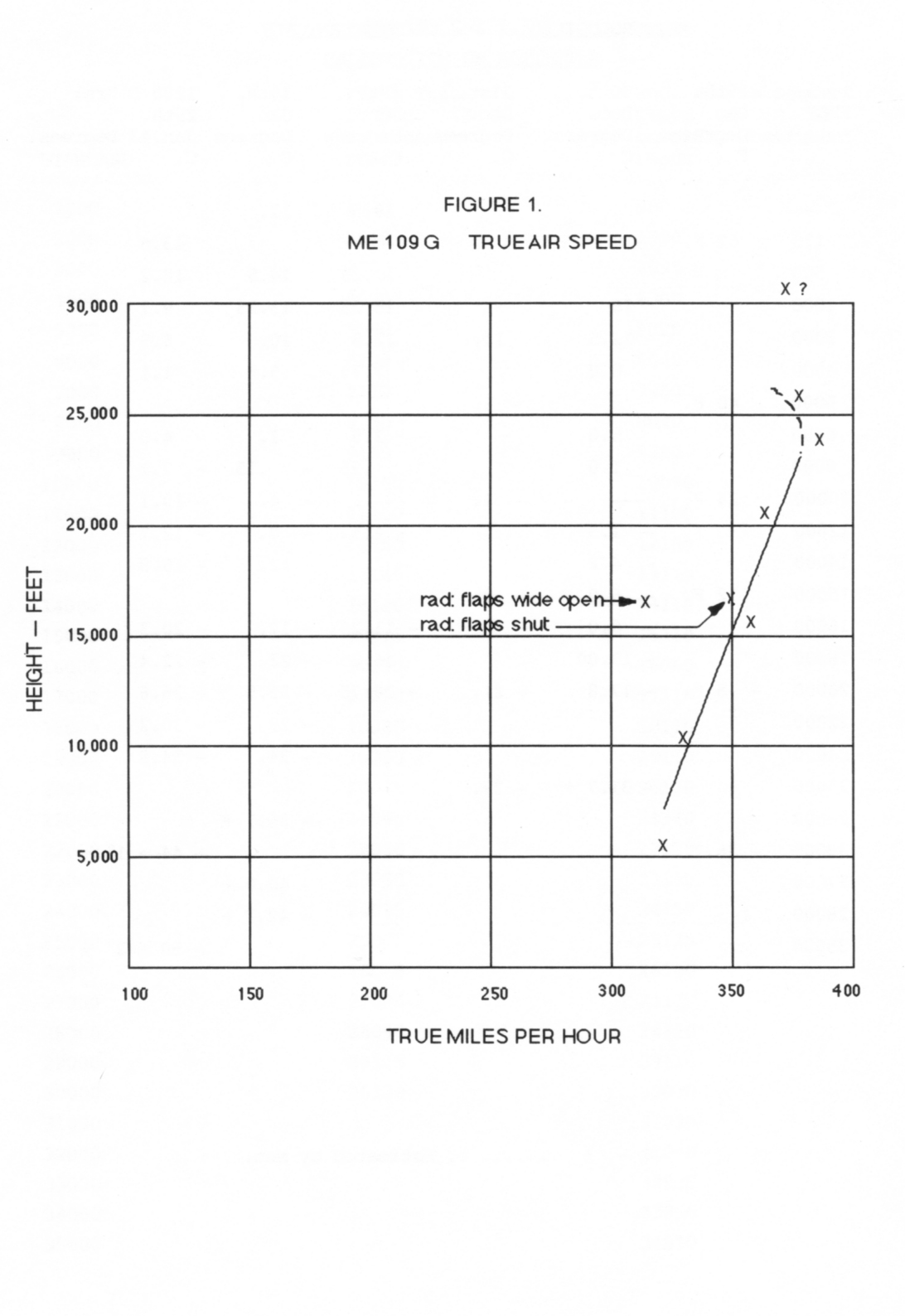
1. An Me.109G captured in the Western Desert was allotted to No. 209 Group for performance tests.
2. The tests were laid down in H.Q., M.E. letter S.54515/OPS dated November 29th 1942 and addressed to A.H.Q., Egypt.
3. The aeroplane was maintained by a squadron maintenance party drawn from a Squadron in the Group, and assistance was given by A.H.Q. Levant, particularly the Meteorological Section, and by No.4 A.R.U.
4. Enemy aircraft section H.Q., M.E. gave much information and assistance, Flight Lieut. MacBean, 87246, was attached and wrote the descriptive part of this report. He has a remarkable knowledge of enemy aircraft.
5. Preliminary tests were chosen to get an outline of the performance and were completed quickly and an interim report was sent in as required by H.Q., M.E. letter. The remaining tests were completed by 29th January 1943.
Results.
6. The new engine (D.B.605) is little better than the old one (D.B.601) in the 109F, the main improvement being an increase in rated height. The fine performance is due largely to the size of the aeroplane. It is remarkably small and light considering the size of the engine.
7. The cockpit is simple. A number of technical controls such as regulation of oxygen flow, adjustment of coolant radiator and oil radiator flaps and airscrew pitch control have been made automatic and need no attention from the pilot. The pilot is then able to give more attention to fighting tactics, teamwork, navigation and practical flying.
8.
The shortcomings of the
aeroplane are, the weakness of the ailerons at high
diving speeds, the weakness of the undercarriage, the
stiffness of the tail trimming gear at high speeds, and
skittishness during landing and take off.
Recommendations.
9.
The small size of the 109G
remains a prime
reason for its good
performance. It is recommended that British aeroplanes should be
designed to be
small, but that skittishness on the ground should be prevented by
having a
nosewheel undercart.
10. British cockpits should be freed of auxiliary technical controls which need the attention of the pilot, and the regulation of oxygen flow, adjustment of coolant and oil radiator flaps and airscrew pitch should be controlled by reliable automatics.
11. It is recommended that a small enemy aircraft test flight should be formed in the Middle East so that performance figures are made available to Air Ministry. The personnel required are suggested as one engineer pilot, one admin. officer, on sergeant pilot, two fitters, two riggers, an electrician, signals and armourer.
Dimensions and Particulars.
Span 32' 7", Length 29' 9": Wing area 173 sq. ft: All up weight (as fighter without wing guns) 6820 lbs. (approx) Wing loading 39.4 lbs. per sq. ft. (approx).
Engine. D.B. 605 A. 12 cylinder inverted 'V' liquid cooled in line, with direct fuel injection. This motor appears identical to the D.B. 601 E except for modified cylinder head blocks and pistons. Below are given performance figures for a D.B. 601 E and D.B. 605 A tested respectively in October 1941 and July 1942. The figures are obtained from German engine history sheets and the significance of the two horse power readings given is not known but may indicate some correction for air temperature or atmospheric pressure.
DB.601E. Tested October 1941.
10. British cockpits should be freed of auxiliary technical controls which need the attention of the pilot, and the regulation of oxygen flow, adjustment of coolant and oil radiator flaps and airscrew pitch should be controlled by reliable automatics.
11. It is recommended that a small enemy aircraft test flight should be formed in the Middle East so that performance figures are made available to Air Ministry. The personnel required are suggested as one engineer pilot, one admin. officer, on sergeant pilot, two fitters, two riggers, an electrician, signals and armourer.
BRIEF
DESCRIPTION OF AIRCRAFT
12.
The Messerschmitt 109G-2 is a
development of the Me.109F-4, from which
it is indistinguishable in the
air. The main difference lies in the engine, that in the Me.109F-4
being
D.B.601 E, while the Me.109G-2 has a D.B.605 A. There are also several
detail modifications but the airframe remains substantially the same.General.
Dimensions and Particulars.
Span 32' 7", Length 29' 9": Wing area 173 sq. ft: All up weight (as fighter without wing guns) 6820 lbs. (approx) Wing loading 39.4 lbs. per sq. ft. (approx).
Engine. D.B. 605 A. 12 cylinder inverted 'V' liquid cooled in line, with direct fuel injection. This motor appears identical to the D.B. 601 E except for modified cylinder head blocks and pistons. Below are given performance figures for a D.B. 601 E and D.B. 605 A tested respectively in October 1941 and July 1942. The figures are obtained from German engine history sheets and the significance of the two horse power readings given is not known but may indicate some correction for air temperature or atmospheric pressure.
DB.601E. Tested October 1941.
Rating |
Revs Per Minute |
Boost. ata lbs. |
Horse Power Nx. No. |
Consumption Litres per hour. |
||
| Take off (5 mins). Climb and Combat (30 mins). Max. Continous. Econ. Cruising. |
2700 2490 2300 1790 |
1.42 1.3 1.15 1.05 |
5.46 3.76 1.63 0.21 |
1425 1236 1017 722 |
1390 1205 993 705 |
381 298 209 |
DB. 605A. Tested July 1942.
Rating |
Revs Per Minute |
Boost. ata lbs. |
Horse Power Nx. No. |
Consumption Litres per hour. |
||
| Take off (5 mins). Climb and Combat (30 mins). Max. Continous. Econ. Cruising. |
2810 2612 2312 2120 |
1.42 1.3 1.15 1.05 |
5.46 3.76 1.63 0.21 |
1496 1321 1076 884 |
1496 1321 1076 884 |
400 310 257 |
The
propeller is a
V.D.M.9 - 12087. Three bladed metal constant-speed with electric pitch
change,
hand controlled or automatic. Diam. 9' 10" Max. blade width 11
5/8".
Mechanical Features.
13. The technical features which affect the operation of the aeroplane are similar to those for the 109F and are briefly recapitulated here for convenience. The 109 is a small aeroplane with a big engine and this largely gets its high performance. The cockpit is correspondingly small. The supercharger is driven through a hydraulic clutch in the same way as the D.B.601. This gives the effect of a multi-speed drive without attention from the pilot. The maximum boost is also automatically limited.
14. The airscrew control can be selected for hand setting or for automatic. The hand control is a rocking switch on the throttle knob. In automatic, the airscrew governor is operated by the throttle lever to give the appropriate revs at all throttle openings, and there is no control for the pilot. The effect on range and engine life from always having the best combination of boost and rev must be good and the pilot at the same time is relieved from attending to the pitch control lever.
15. The airscrew is electrically operated, and the handbook warns against overspeeding if a dive is started suddenly, so that the pitch change is presumably slow like our electric airscrews.
16. The flaps of both the oil and coolant radiators are thermostatically controlled. The operating fluid is engine oil for the oil radiators, and hydraulic system oil for the coolant radiators' flaps. Control of the coolant radiator flaps by the pilot is possible but normally he will set it to automatic. The flap operation is mechanical, by a wheel and the undercarriage retraction is hydraulic without emergency hand pump.
Cockpit.
17. The fuselage is clearly designed to be as small as possible to give the maximum performance, and consequently the cockpit is rather cramped for anyone over 6 feet tall. The controls are laid out so that all ordinary ancillary controls are worked by the left hand, the right side of the cockpit having only switch buttons. This layout, combined with the automatic setting of airscrew pitch and of coolant flaps for water and oil, simplifies the task of the pilot.
18. Details of the controls, which are similar to those on some allied aircraft, are given in the German handbook of which a translation is held in the Enemy Aircraft Section, H.Q., M.E. A photo of the cockpit, consisting of three photos put together, is Figure 6. The rudder pedals are level with the seat so that the pilot is in a good position to resist acceleration; all ancillary controls are convenient to reach and to use.
19. Owing to the inverted engine, the top of the front cowling is narrow and the view forward on each side is reasonably good. The instruments supplied are:‑
Flying
combined Artificial horizon and turn indicator
repeater compass
altimeter
air speed indicator
Technical
Boost gauge
R.P.M.
Airscrew pitch indicator
Oil and coolant temp. (combined)
Fuel and oil pressure (combined)
Clock
Undercarriage lights.
Undercarriage mechanical position indicator.
Fuel warning light (20 minutes to go).
20. The hood is small and has no curved surfaces. The thick perspex panels are flat and allow a good view through them. A sliding panel on top and each side allows a clear view in bad conditions. The hood is jettisoned by a red lever on the left side.
Armour.
21. This is almost identical to the Me.109F-4 and consists of one flat and one curved 10 m.m. plate protecting the back and top of the pilot's head. Three plates, the upper one 8 m.m. and the lower 24 m.m. [Note: This must be two 4 m.m. thick plates as noted elsewhere] protect the pilot's back. A 63 m.m. bullet proof glass shield set at approx. 60° is mounted 13 m.m. behind the 8 m.m. plexiglass windshield. A dural bulkhead consisting of 30 layers of 0.8 m.m. sheet bolted together is fitted to the lower 2/3 of the fuselage cross section. The fuel tank is 'L' shaped and is situated behind and below the pilot. It is of flexible rubber construction enclosed in a plywood box for support and consists of inner and outer layers of hard black rubber and a centre layer of soft self sealing rubber. The capacity is 85 gallons. The oil tank is of unprotected light alloy, ring shaped, fits round the airscrew reduction gear, and holds 8 1/2 gallons. The coolant header tanks are also of unprotected light alloy and are mounted on either side of the crankcase. Occasionally fuel tanks made of unprotected light alloy have been found on Me.109'Es and F's and once on a G. [Note: This was an occasinal trait of lightened high altitude fighters.]
Radio.
22. The standard German fighter R/T set, FUG VII a, is fitted as on the Me.109F. For further details reports are available through the Enemy Aircraft Section, H.Q., M.E.
Oxygen.
23. The standard Draeger Unit as on Me.109F is fitted, the supply being drawn from 3 light alloy bottles of normal type mounted on the bulkhead behind the fuel tank. The oxygen-air mixture is regulated by a barometric capsule up to 33,000 feet, above which height pure oxygen is delivered, the rate of flow being controlled all the time by the pilot's breathing, though a hand operated button is provided to give a sudden extra supply if desired at any time.
Compass.
24.
The layout is the same as the
Me.109F and consists of a Patin Master compass fitted in the
rear fuselage behind the laminated dural bulkhead which
repeats electrically to a slave compass on the instrument
panel.
Guns.
25. Gun Installation. This is identical to the Me.109F which has been fully reported previously, and consists of 2 x M.G. 17, 7.92 m.m. machine guns mounted over the engine firing through the airscrew disc, and 1 M.G. 151, 20 m.m. cannon mounted on the rear of the engine and firing through propeller hub. 200 rounds may be carried for the cannon and 500 rounds for each machine gun. M.G. 17 are cocked and fired by compressed air, electrically controlled. The M.G. 151 is cocked and fired electrically. Wiring is also provided for the installation of two more M.G. 151, 20 m.m. cannon, one under each wing, just outboard of the wheel recesses. These guns have, however, only once been found fitted.
26. Synchronisation. Of the two M.G. 17's is mechanical by flexible push rods enclosed in tubes operated by cams driven from the accessory drive at the rear of the engine.
27. Harmonisation. As the axes of the M.G. 17's are only 14" apart and these are only 17" above the axis of the M.G. 151 it would appear that harmonisation is scarcely neccessary. At 50 yards there was no apparent converging of the trajectories of the M.G. 17's but it was not possible to check the trajectory of the M.G. 151 which had moreover been removed and replaced by another gun making any estimate of doubtful value.
28. Stop Butt Trials. Since the M.G. 151 and M.G. 17 have been fully tested and reported on by Woolwich and rates of fire and velocities ascertained, it is not considered necessary to carry out further trials. Reports are available through H.Q., M.E. Enemy Aircraft Section.
29. Re-arming. Re-arming is simple and could be carried out by four men in under ten minutes. Operations consist of removing empty belts and cases from cannon and M.Gs. via two quickly detachable trays under fuselage. Lifting both sides of engine cowling (three quick release fittings on each side). Replacing old M.G. magazines with new and fitting belts (the M.Gs. are very accessible). Removing cannon breach cover in cockpit (three quick release fittings) fitting new belt (magazine in port wing accessible via two quick release covers). Feeding belt through guide and inserting in breach. Closing breach. Replacing cover. Lowering and securing engine cowlings. Gun cleaning could be carried out if necessary during or in between any of these operations.
30. Maintenance. The guns are quickly removable for maintenance and this should provide no difficulties. Both guns and cannon are very simple in operation being recoil and having a minimum of working parts.
31. Cine-camera. Provision is made in the electrical circuit for a cine-camera but these are not fitted as a rule and on only two aircraft have windows in the port wing, just outboard of the wheel recesses, been found for this purpose.
32. Sights and Sighting. A Revi C/12/D reflector sight is fitted (as in the 109F). This is a simple sight having no range computing device. It is provided with a glare shield and dimming control, and an emergency ring and bead sight attached to the right hand side.
TECHNICAL
TRIALS.
Manoeuvrability.
33. The elevators harden up at high speeds and retrimming is necessary, which is difficult as the trim wheel hardens up and becomes almost sold in a dive. Some force is needed on the stick at high speeds, but accelerations as great as the pilot can stand can be put on.
34. The ailerons are satisfactory up to a moderate dive, and after that were used charily owing to the warning in the handbook of their weakness. Comparative combat trials are needed to complete this section of the report.
Take off.
35. The aeroplane tends to swing to the left towards the end of the take off and firm right rudder is needed. The take off is very good so that the throttle can be opened slowly and it is then easier. A normal pilot in still air will take 350 yards.
Stalling Speed.
36. Stalling speed is 102 m.p.h. indicated flaps and wheels down, and 112 m.p.h. with flaps and wheels up. With flaps and wheels up, the ailerons control becomes distinctly lighter at about 140 m.p.h. when the slots open.
Trim.
37. The trim is effective and not too sensitive. At high diving speeds it becomes almost solid.
Landing.
38. Approach should be made at 120 m.p.h. indicated.
39. The aeroplane is rather skittish and the pilot concentrated on keeping straight and did not look at the A.S.I. in the cockpit to see speed at touch down.
40. From the known stalling speed, the speed at touchdown can be deduced as 105 to 110 m.p.h.
41. The minimum landing run to be expected in still air with a normal pilot is 550 yards.
Performance.
42. Climb and speed readings are tabulated on subsequent pages. Results are also plotted as Fig. 1. Speed Fig. 2. Rate of climb Fig. 3. Rate of climb — Different speeds Fig. 4. Rated Height Fig. 5. Time to Height. All tests were done at maximum engine power. (Germans have cancelled maximum emergency power, apparently owing to engine failures.)
Dive.
43. The dive and shallow dive are very fast. Controls become heavy but large deflections are still possible at 350 m.p.h. indicated. N.B. The handbook warns against rough movement of aileron controls during dive and particularly during recovery, as likely to cause a crash. Limit speed 467 m.p.h.
Endurance.
44. The petrol consumptions are tabulated on subsequent page. Duration must vary greatly with operational conditions and the time spent in dog fighting; the duration to be expected normally is one hour.
Instrument Flying.
45. The complete standard German set of instruments was not fitted. Instruments flying is judged to be normal and straightforward.
Night Flying.
46. Cockpit and exhaust shielding are similar to the 109 F.
Enging Starting.
47. The engine was always started by hand. It often started at the first attempt and always started (when in our hands) at the second or third attempt. An experienced crew can probably count on a start in good weather conditions at the first attempt.
48. A small separate tank is provided for the priming pump which can be filled with specially volatile starting fuel for starting in bad weather conditions.
(signed) G.M. BUXTON Gp. C. (?)
ME. 109 G - 2 (TROP).
FIRST TEST FLIGHT. 0905 - 0955B HOURS 29th DECEMBER 1942
FIRST TEST FLIGHT. 0905 - 0955B HOURS 29th DECEMBER 1942
1. The Me. 109 G. was made serviceable by 451 Squadron Detachment.
2. The aeroplane had been restored to standard good condition except that the oil radiator flap was locked open as received, as the functioning of the thermostatic control was apparently bad; no oil thermometer was available; there was a splinter hole and score mark in one airscrew blade.
3. Close examination of the airscrew blade is therefore made between flights.
4. During take off, there is a marked swing to the left which occurs towards the end of the run as full power is given. Acceleration is quick and take off run fairly short.
5. After take off, climb was started, partial climbs being made at each height; full speed level runs were made mostly on the way down. The figures are tabulated in Appendix "A" and the air temperatures for compiling true speeds are tabulated in Appendix "B".
6. The air filter was cut out at about 8000 feet and was put in again after all tests had been done, before coming in to land.
7. The propeller pitch control was left in automatic throughout, and the figures of boost and revs given in Appendix "A" are therefore those set by the automatic mechanism.
8. The radiator flaps were left in automatic and kept the temperature at 80°C most of the time in the easy conditions of cruising used between test runs. The maximum temperature seen was 100°.
9. The altimeter readings were not exact as the needle was swinging.
10. At 15000 to 20000 feet in the climb, the engine hesitated and petrol pressure was seen to be low. This immediately rose on switching on the electric pump, and the engine then ran normally.
11. The engine has some rough periods, but usually, and particularly at high r.p.m., runs sweetly.
12. Owing to the high rate of climb, it is necessary to allow a margin of up to 3000 feet to settle down into a steady climb; thus for timing a climb from 15000 to 17000 feet it is desirable to pull up to climbing speed (e.g. 150) at 12000 feet. In full speed level flights, speed is picked up quickly.
13. The control is steady and it is easy to maintain accurate speed with reasonable care.
14. After almost 45 minutes flying, the red fuel shortage (15 minutes to go) warning light showed. Owing to the fuel swishing about, the light shows intermittently and is an effective warning.
15. In the approach to landing, torque can be distinctly felt and so the engine should be opened up slowly when "rumbling".
ME.109
G-2 (TROP).
SECOND TEST FLIGHT. 1415 - 1530B HOURS. 30th DECEMBER 1942.
SECOND TEST FLIGHT. 1415 - 1530B HOURS. 30th DECEMBER 1942.
1. A series of 1000 feet timed climbs were done at various heights. Owing to the high rate of climb, and to the fact that the sensitive altimeter needle was swinging over a considerable arc, the time was not likely to be accurate, and therefore climbs at certain heights were repeated for a height difference of 2,000 feet so that any error in timing would have less effect.
2. The cooling flaps on the radiator are automatically controlled and they open as the engine temperature rises. They are big enough to cause considerable drag when wide open. Therefore they will cause more drag on a long continuous climb and so decrease the performance. To test this point, a long battle climb will be made.
3. Tests are being continued in cloudy weather as the effects of the up currents and bumps are not thought to be so important as speed in getting some preliminary figures.
ME.109
G-2 (TROP).
THIRD TEST FLIGHT. 0920 - 1015B HOURS 31st DECEMBER 1942.
THIRD TEST FLIGHT. 0920 - 1015B HOURS 31st DECEMBER 1942.
1. On the third tests, repetitions were made of climbs and level speeds which seemed necessary to fill gaps in the performance curves plotted from the previous two test flights. A test was also made to find the rated altitude at 1.3 at: boost and corresponding revs in automatic (i.g. interconnected) airscrew control.
2. During the climb from 30070 to 32000 feet, the cooling flaps were seen to be wide open, owing apparently to a sticky thermostat. They were adjusted to normal position by using the manual control but the rate of climb obtained must have been somewhat reduced by this.
3. Some variation was noticed in the airscrew r.p.m. presumably due to the automatic control functioning slightly irregularly.
4. The rated height of the engine was found by doing a steady climb at 200 mph. indicated and noting the boost pressure at each thousand feet. The automatic boost control keeps the boost constant below rated height, and it decreases above. By plotting a graph of boost against height, the line of the decreasing boost can be drawn and this meets the position of 1.3 boost at 21300 feet which is taken as the rated height as governed r.p.m. (2750).
5. Level speed was tested at 23,200 feet (true) which gave 262 m.p.h. indicated equal to 378 m.p.h. computed.
ME.109 G - 2.
FOURTH TEST. 1505 - 1615B HOURS 17th JANUARY 1943.
FOURTH TEST. 1505 - 1615B HOURS 17th JANUARY 1943.
1. The original good maintenance crew under Sergeant Osborne left with their squadron, and a new crew has taken over. No.4583 Sergeant Dill-Franzen of No. 7 S.A.A.F. came to change the airscrew. The new airscrew is in normal adjustment and appears to give the same results.
2. During take off, the engine was opened up nearly to full power, and firm right rudder was needed to stop swing to left. Take off run is tabulated. Landing was made in reasonable tail down attitude, nearly three point, and brakes were initially applied to stop swing, and then both brakes were put on firmly. Landing run is tabulated.
3. Tests were then made (at 5,000 feet) on stalling. Stall was read first with flaps and wheels retracted, then with flaps and wheels fully down. The figures show that 120 m.p.h. (195 km/hr) is the minimum safe speed of approach, and only gentle turns should be made below 150 m.p.h. (240 km/hr).
4. Partial climbs from 4,000 to 6,000 feet were then made to find best climbing speed. Radiator flaps were set with the top flap level with the wing flap (control on "RUNE"). An inexplicable quick climb at 160 m.p.h. was repeated and a more normal time was got. Air intake filter was in use.
5. Partial climbs were then made from 19,000 to 21,000 feet (Altimeter). First 140 m.p.h. climb was probably slow as engine hesitated owing to low fuel pressure which was raised by switching on electrical fuel pump. A repetition was also slow as boost fell during climb owing possibly to slight stickiness of automatic boost mechanism. A similar slight fall of boost pressure happened at the 160 m.p.h. climb, but not on the two others, on one of which r.p.m. was slightly high. The intake filter was of course out for this test. The radiator flaps were in "automatic" and were controlling satisfactorily, the temperature being low and the opening small. The opening did not vary by more than about an inch during this series of climbs.
6. The engine was rather rough at times at low power, but still is reasonably smooth at full power.
5A. Meteorological Office, A.H.Q. Levant was asked if any currents could occur which might account for the irregular results at 5,000 feet. They state that an up current occurred locally between surface and 9,000 feet with a maximum of 400 feet per minute at 6,000 feet.
FOURTH
TEST OF ME.109G-2
(TROP) 1 HOUR 10
MINUTES
17th JANUARY 1943Take off run Approx. 270 yards.
<>
Wind 12 m.p.h. 47° to take off direction.
Temperature 18.5° C. Millibars sea level 1014. Height 130 feet.
Landing run Approx. 430 yards.
Nearly three point attitude on touching and brakes used firmly.
Wind 12 m.p.h. 20° to landing direction.
Temperature 18.5° C. 1014 Millibars sea level. Height 130 feet.
Stall. With flaps and wheels up. Port
aileron control is lost at 115
m.p.h. indicated. Nose dropped
at 110 m.p.h. indicated.
With flaps and wheels down.
Ailerons duff at 112 m.p.h.
indicated.
Nose drops at 102 m.p.h.
indicated.
Take off run. 196 yards approximately.
Wind. 15 m.p.h. dead ahead.
Temperature. 17 degrees C. 1011 Millibars sea level. Height 130 feet.
Landing run. 440 yards approx.
Wind. 15 m.p.h. dead ahead.
Temperature. 17 degrees C. 1011 Millibars sea level. Height 130 feet.
Wind 12 m.p.h. 47° to take off direction.
Temperature 18.5° C. Millibars sea level 1014. Height 130 feet.
Landing run Approx. 430 yards.
Nearly three point attitude on touching and brakes used firmly.
Wind 12 m.p.h. 20° to landing direction.
Temperature 18.5° C. 1014 Millibars sea level. Height 130 feet.
Stall. With flaps and wheels up. Port
aileron control is lost at 115
m.p.h. indicated. Nose dropped
at 110 m.p.h. indicated.
With flaps and wheels down.
Ailerons duff at 112 m.p.h.
indicated.
Nose drops at 102 m.p.h.
indicated.
FIFTH
TEST.
Take off run. 196 yards approximately.
Wind. 15 m.p.h. dead ahead.
Temperature. 17 degrees C. 1011 Millibars sea level. Height 130 feet.
Landing run. 440 yards approx.
Wind. 15 m.p.h. dead ahead.
Temperature. 17 degrees C. 1011 Millibars sea level. Height 130 feet.
FIFTH & SIXTH TESTS.
Take off
run and landing run were measured.
Partial climbs were made at 27,000 feet, which is the greatest height at which Met. Temperatures were available.
A level speed test was also made at 27,000 feet.
A level speed test was made at 16,500 feet first with radiator flaps open and then with them closed. Speeds are plotted on the speed curve to show their effect.
The sixth test, which was to be a climb to height had to be stopped before any readings were got, because the hood jettisoned itself.
ME.109, G-2 (TROP).
SEVENTH AND EIGHTH TESTS. 0935 - 1030B HOURS 29th JANUARY 1943
SEVENTH AND EIGHTH TESTS. 0935 - 1030B HOURS 29th JANUARY 1943
SEVENTH TEST.
A climb to height was made to conclude the programme of partial climbs.
The climb was made at full throttle with the airscrew in automatic.
stop watch was started quickly after taking off and operating undercarriage retracting button, i.e. about three quarters of the length of the runway. Subsequent readings were made by looking at the watch. The aerodrome is at 130 feet and the altimeter was set to 130 feet (1015 Millibars) before take off.
Between twenty and twenty-five thousand feet the coolant temperature was seen to be low and the radiator flaps were wide open. This must have temporarily reduced the rate of climb. The automatic thermostat must have stuck, and the radiator flaps were set by hand to a small opening.
To keep the (unknown) oil temperature down, the climb was made at 170 m.p.h. up to 25,000 feet and reduced to 150 m.p.h. from 25,000 to 35,000 feet.
The oil pressure was steady throughout, one division above minimum.
EIGHTH TEST.
Test of stall was made with wheels and flaps up and wheels and flaps down.
UP. About 120 m.p.h. the aircraft began to lose height. The nose did not fall appreciably and there was no tendency to drop a wing and there was still aileron control.
DOWN. Just below 105 m.p.h. the aircraft began to lose height but again it showed no vices and aileron control was maintained.
A slight and quick vibration was noticed when just approaching the stall. Several bursts of motor were given when near the stall but it was always possible to check any tendency to swing.
[Reproduction of large tables that would be included in the end of the report, showing meterological, calibration, misc. small details about these test, ie. see from 20. to 30., which are generally just repeating the same Figures 1-5, just in tabulated from has been left out from this reproduction as they contain little useful information. They may be added to this report later on.]
Last updated 21
September 2006.
Work in progress.
All rights reserved.
email at : kurfurst@atw.hu
Total Site Page loads :
Work in progress.
All rights reserved.
email at : kurfurst@atw.hu
Total Site Page loads :